Environmental Monitoring and Irrigation Linkage Reference Solution
Page Guide
1. Solution Overview
1.1. Industry Pain Points
Facility agriculture and large-scale planting commonly face three types of problems:
- Manual greenhouse patrols: Environmental data such as temperature and humidity, soil moisture, and light relies on scheduled manual inspections and records. Monitoring gaps easily occur at night and during extreme weather, and heat-stress or frost damage is a loss the moment it is discovered.
- Experience-based irrigation: Watering and fertilizing depend on veteran farmers' intuition. Differences in water demand across plots and growth stages cannot be responded to precisely, so water and fertilizer waste coexists with crop stress.
- Device silos: Fans, wet curtains, film-rolling motors, water-fertilizer integrated machines, and solenoid valves come from different vendors with different protocols, each with its own remote control or control cabinet, making unified linkage driven by environmental data impossible.
1.2. Solution Positioning
This solution centers on the FastBee IoT platform. Environmental sensors and irrigation and environmental-control devices are connected uniformly, data is standardized through thing models, and the "monitoring data → judgment → execution" chain is solidified into automatic rules through scene linkage, achieving:
- 7×24 continuous monitoring of greenhouse and field environments, with anomalies automatically alarmed to the responsible person;
- Thresholds such as soil moisture and greenhouse temperature trigger automatic start/stop of irrigation and environmental-control devices, with manual override retained;
- Monitoring dashboards, mobile app, reports, and product traceability presented in an integrated way, with support for on-premises deployment so data never leaves the park.
2. System Architecture
The solution adopts a four-layer architecture of "device layer — access layer — platform layer — application layer":

2.1. Device Layer
Includes weather stations (temperature and humidity, light, rainfall, wind speed), soil temperature-humidity and EC sensors, pest monitoring lights, water-fertilizer integrated machines, solenoid valves, water pumps, fans, wet curtains, film-rolling motors, and GB28181-compliant bullet and dome cameras. For device selection, prioritize IP65-or-better protection and wide-temperature operation; in high-temperature, high-humidity environments, the service life of cheap probes is often far below the nominal value.
2.2. Access Layer
The FastBee IoT gateway handles protocol conversion and edge computing: upward it communicates with the platform over MQTT, and downward it is compatible with Modbus RTU/TCP, TCP, UDP, WebSocket, and other access methods. For scenarios with scattered greenhouses and inconvenient power supply, battery- or solar-powered nodes can aggregate to the gateway over LoRa, and a single gateway can carry dozens of collection nodes. When the gateway loses connectivity, it caches data locally and maintains the configured linkage logic, then automatically backfills after recovery.
2.3. Platform Layer
The FastBee platform is responsible for full device lifecycle management and data flow:
- Thing Model: Abstracts each device type into properties, methods, and events, with measurement points such as soil moisture and valve opening modeled uniformly;
- Rule Engine and Scene Linkage: Threshold judgment, multi-point voting, scheduled tasks, and cross-device linkage are configured here;
- Alarm Center: Pushes alarms by severity, supporting notification to people and closed-loop handling;
- Video Monitoring: Connects cameras over GB28181, supporting PTZ control, stream pushing, and playback.
2.4. Application Layer
Provides role-oriented monitoring dashboards (park overview, trend curves, device status), a PC management console (device, plot, batch, and task management), a mobile app (real-time data, remote control, alarm receiving), and a product traceability H5.
3. Core Features
3.1. Environmental Data Collection
Sensors report temperature and humidity, soil moisture, light, CO₂, and other data at configured intervals. The platform stores the data uniformly and supports historical curve queries and report export, providing the data foundation for farming decisions and traceability.
3.2. Remote Control of Irrigation and Environmental Control
Devices such as solenoid valves, water pumps, water-fertilizer machines, fans, and wet curtains support remote start/stop from both the platform and the mobile app. Scheduled tasks can be configured (for example, 30 minutes of drip irrigation every morning), and every control action and its execution result is recorded in the device log.
3.3. Scene Linkage
Scene linkage is the core of this solution: when monitoring data meets conditions, device actions are triggered automatically, such as "soil moisture below the threshold and no rain in the next two hours → open the solenoid valve of the corresponding plot" or "greenhouse temperature above 32℃ for 10 minutes → start the fans and wet curtains". In production environments, multi-point voting and minimum run intervals are recommended to prevent actuators from frequent start/stop caused by single-point drift; see the Scene Linkage documentation for details.
3.4. Alarm Notification
Events such as sensor offline, data out of range, and linkage execution failure generate alarms by severity, pushed to the responsible person through platform messages and the mobile app. Critical alarms support acknowledgment and handling records, forming a closed loop.
3.5. Monitoring Dashboard and Mobile App
The monitoring dashboard displays real-time environmental data, device online status, and alarm dynamics partitioned by plot, suitable for permanent display in the park control room. The mobile app covers data viewing, device control, and alarm receiving, so managers can verify the site directly on their phones and intervene with one tap while patrolling the greenhouses.

3.6. Video Monitoring and Traceability
Field and greenhouse cameras are connected over GB28181, supporting PTZ direction and zoom control, real-time stream pushing, and historical playback. The traceability module associates production area, plot, germplasm, farming tasks, and monitoring data to generate batch traceability codes; scanning the code reveals the full record.
4. Device Access
4.1. Access Procedure
- Modeling: Create a product on the platform and define a Thing Model; for example, a soil sensor defines humidity, temperature, and battery properties, and a solenoid valve defines a switch property and switch methods;
- Access: The gateway configures collection channels according to each device's actual protocol; Modbus devices are configured with register mapping, and actively reporting devices connect directly over MQTT;
- Registration: Register devices in Device Management, bind them to products and plot groups, and confirm they are online and reporting data normally;
- Linkage: Configure trigger conditions and execution actions in Scene Linkage, validating on a small scale first before rolling out.
4.2. Irrigation Linkage Example
The following diagram shows a typical "sense — decide — act" chain: a soil moisture node reports through the gateway, the platform rule engine judges according to thresholds and linkage policies, automatically opens the irrigation valve, and pushes an alarm notification at the same time.
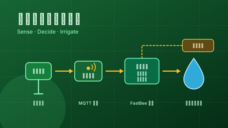
Configuration recommendations:
- Deploy 2-3 soil moisture measurement points per plot and use majority voting to avoid false triggers from single-point failure or drift;
- Set minimum run and stop intervals for motor-driven actuators such as water pumps and fans to protect device lifespan;
- Push every linkage action as a notification to people, and keep a one-tap manual override entry on the mobile app.
5. Deployment and Implementation
- Site survey: Inventory the distribution of greenhouses and plots, existing device protocols, and power and network conditions, and determine gateway placement and communication method (wired, 4G, or LoRa aggregation);
- Platform deployment: FastBee supports on-premises deployment; in conventional environments installation is completed through Docker one-click deployment, with data kept locally in the park;
- Device access and joint debugging: Connect devices in batches following the procedure in Section 4, verifying data reporting and remote control greenhouse by greenhouse;
- Linkage gray rollout: Enable linkage rules in a single greenhouse first and observe for one to two weeks; after confirming the thresholds are reasonable, replicate them to all greenhouses;
- Training and handover: Train managers on the dashboard, mobile app, and alarm handling process, and deliver the thing model and linkage rule inventory.
The overall timeline depends on site scale; small and medium-sized parks can typically go from deployment to linkage go-live within a few weeks. For a quick trial, refer to Quick Start.
6. FAQ
There is no mains power or network in the greenhouse. How do the sensors connect?
Use battery- or solar-powered collection nodes that aggregate over LoRa to the nearest gateway, which then reports to the platform over 4G or a wired network. The gateway supports offline caching and local linkage, and automatically backfills data after connectivity recovers.
Can fans, wet curtains, and water-fertilizer machines from different vendors be linked in a unified way?
Yes. The IoT gateway is compatible with common protocols such as Modbus, TCP, UDP, MQTT, and WebSocket. Once devices from different vendors are connected uniformly through the gateway, they are abstracted into thing models, and scene linkage is orchestrated against thing model properties and methods, decoupled from device brands.
What if automatic irrigation is triggered by mistake?
Configure multi-point voting, duration, and minimum run intervals for trigger conditions; linkage actions push notifications simultaneously and retain manual override. In the early stage, run in "alarm + manual confirmation" mode, and switch to fully automatic only after the thresholds have proven stable.
Does the solution support on-premises deployment? Will data leave the park?
Yes. The FastBee platform can be deployed entirely on-premises on servers inside the park; monitoring data, video streams, and traceability data all stay local. When remote access is needed, it can be opened independently according to the park's network policy.