


IEC103 Access via TCP Gateway
This article reorganizes an existing operation manual into an online operation reference. Operations marked as expected or not executed in the original must still be verified against the actual environment.
Complete IEC103 TCP-gateway ten-point reporting, two controls with independent states, manual reconnection, general interrogation, and history queries.
Before you begin: You have product, device, model, publish, control, and history permissions; the local application, single-node FMQ, and FMQX Web are available, and this device's formal point table has been obtained.
Purpose and Gateway Connection Direction
This tutorial uses an already configured protection collection device. For first-time access, fill in according to the examples; existing resources can be verified directly, then continue from the publish and report sections.
The platform selects the gateway device type, the IEC103 data format, and the TCP_GATEWAY transport recipe; the FMQX Web device actively connects to FMQ 8888 as a TCP client.
FUN160, INF1 to 10 correspond to platform point addresses 40961 to 40970, and only Protection 1 allows control. true displays as Closed and false as Open.
1. Configuring the Gateway Product, Device, and Ten-Point Mapping
The model English translation is a required field and must be filled in completely before saving. Each protection point uses an independent property; all ten points have history enabled, and only Protection 1 allows write.
1. Setting the Gateway Device Type
Location: Device Management → Access Devices → Advanced Configuration Steps: In the product advanced configuration, set the Product Type to Gateway Device.
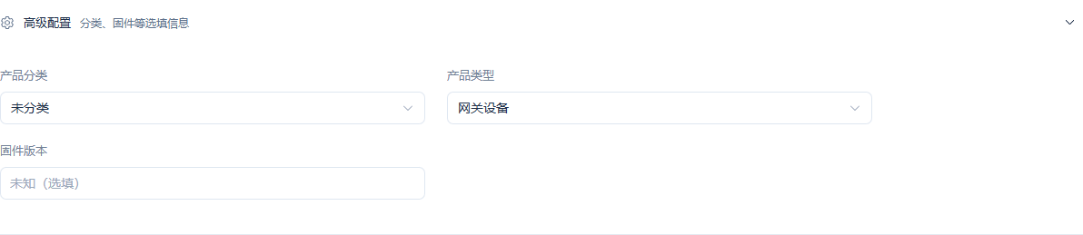
The product type is Gateway Device; category and firmware version are optional depending on the business.
Screenshot Highlights
| Field / Control | Description |
|---|---|
| Product Type | Select Gateway Device to match the TCP gateway combination later. Required · Fill in: 网关设备 |
| Product Category | Optional by business classification; it does not replace the protocol selection. Required · Fill in: Fill according to the implementation plan · Example: 未分类 |
| Firmware Version | Optional according to the actual situation; this example does not perform an upgrade. Required · Fill in: Fill according to the implementation plan · Example: Optional |
| Category and Firmware | Used to complete "Setting the Gateway Device Type". Required · Fill in: Optional according to the actual situation |
2. Verifying the Saved Gateway Protocol
Location: IoT → Device Management → Product Management → Product Details → Basic Information Steps: Verify the data format IEC 60870-5-103 and the transport TCP_GATEWAY.
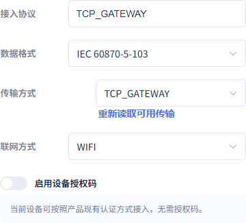
The platform uses IEC103 and TCP_GATEWAY; the network access method WIFI and the device authorization code are separate management parameters.
Screenshot Highlights
| Field / Control | Description |
|---|---|
| Data Format and Transport | The platform gateway device selects the native IEC103 and TCP_GATEWAY recipe. Required · Fill in: Fill according to the implementation plan · Example: IEC 60870-5-103 / TCP_GATEWAY |
| Network Access Method | Records the device's network access method; it does not change TCP protocol transport. Required · Fill in: Fill according to the implementation plan · Example: WIFI |
| Device Authorization Code | Selected by product access rules; off in this example. Required · Fill in: Fill according to the implementation plan · Example: Off |
| Data Format | Used to complete "Verifying the Saved Gateway Protocol". Required · Fill in: IEC 60870-5-103 |
| Transport | Used to complete "Verifying the Saved Gateway Protocol". Required · Fill in: TCP_GATEWAY |
3. Verifying the Model Name and the Required English Translation Entry
Location: IoT → Device Management → Product Management → Product Details → Function Definition → Property Editing Steps: Verify the Protection 1 name, identifier, and the model translation input box.
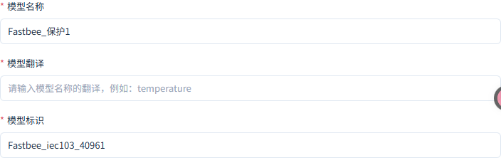
The name and identifier are filled in; the English translation in the image is still empty and must be completed before saving.
Screenshot Highlights
| Field / Control | Description |
|---|---|
| Model Name and Identifier | Each point is an independent property; the model English translation is required and still needs to be completed in the image. Required · Fill in: Fill according to the implementation plan · Example: 保护1 / Protection1 |
| Model English Name | The English name is required; fill it in before saving the permission settings. Required · Fill in: Fill according to the implementation plan · Example: Protection1 |
| Model Name | Used to complete "Verifying the Model Name and the Required English Translation Entry". Required · Fill in: 保护1 |
| Model English Translation | Required; the input box in the screenshot is still empty. Required · Fill in: Protection1 (filling example) |
4. Setting the Boolean Display Text
Location: IoT → Device Management → Product Management → Product Details → Function Definition → Data Type Steps: Select the Boolean type, displaying false as Open and true as Closed.
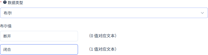
false corresponds to Open, true corresponds to Closed.
Screenshot Highlights
| Field / Control | Description |
|---|---|
| Permission and History | Only Protection 1 is writable; all ten points have history enabled; true is Closed, false is Open. Required · Fill in: Fill according to the implementation plan · Example: Protection 1 writable; history on for all ten points |
| Data Type | Used to complete "Setting the Boolean Display Text". Required · Fill in: 布尔 |
| false / true Display | Used to complete "Setting the Boolean Display Text". Required · Fill in: 断开 / 闭合 |
5. Manually Filling in the Device Information
Location: Device Management → Access Devices → Manual Add Steps: Open Manual Add from Device Management and fill in the device name, owning product, and unique number.
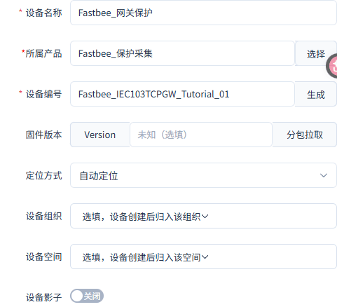
The device's owning product matches the protocol configuration, and the device shadow is off.
Screenshot Highlights
| Field / Control | Description |
|---|---|
| Device Number | Keep identical to the protocol-bound clientId. Required · Fill in: FastBee_IEC103TCPGW_Tutorial_01 |
| Device Shadow | Off in this example; control requires the device to be truly online. Required · Fill in: Fill according to the implementation plan · Example: Off |
| Device Name | Used to complete "Manually Filling in the Device Information". Required · Fill in: 网关保护 |
| Owning Product | Used to complete "Manually Filling in the Device Information". Required · Fill in: 保护采集 |
6. Binding the Device and the Link/Station Address
Location: IoT → Device Management → Product Management → Product Details → Device Protocol Configuration → Device Binding Steps: Select the gateway protection device, verify the device identifier, set the common address and link address to 1, and enable.
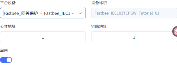
This binding groups link data under the same device, with common address 1 and link address 1.
Screenshot Highlights
| Field / Control | Description |
|---|---|
| Device Binding | Bind the same gateway protection device; the device identifier matches this device's number. Required · Fill in: Fill according to the implementation plan · Example: Device number identical to clientId |
| Common Address | The station address of the protection device; keep the platform and the device consistent. Required · Fill in: Fill according to the implementation plan · Example: 1 |
| Link Address | The FT1.2 link identifier; keep both ends consistent. Required · Fill in: Fill according to the implementation plan · Example: 1 |
| Device Number | Used to complete "Binding the Device and the Link/Station Address". Required · Fill in: FastBee_IEC103TCPGW_Tutorial_01 |
| Common Address / Link Address | Used to complete "Binding the Device and the Link/Station Address". Required · Fill in: 1 / 1 |
7. Configuring the Protection 1 Point
Location: IoT → Device Management → Product Management → Product Details → Device Protocol Configuration → Point Mapping Steps: Map information object address 40961 to Protection 1, with type BOOLEAN, scale 1, offset 0, and enable.
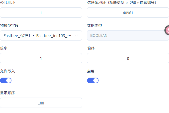
Common address 1, FUN160, INF1 correspond to 40961; this point allows control.
Screenshot Highlights
| Field / Control | Description |
|---|---|
| Common Address | The station address of the protection device; keep the platform and the device consistent. Required · Fill in: Fill according to the implementation plan · Example: 1 |
| FUN and INF | FUN160, INF1 to 10 correspond to platform point addresses 40961 to 40970. Required · Fill in: Fill according to the implementation plan · Example: Platform address=FUN×256+INF |
| Point Mapping | All ten points are type BOOLEAN, scale 1, offset 0; only 40961 allows write. Required · Fill in: Fill according to the implementation plan · Example: BOOLEAN / 1 / 0 |
| Information Object Address | Used to complete "Configuring the Protection 1 Point". Required · Fill in: 40961 |
| Protection Point | Used to complete "Configuring the Protection 1 Point". Required · Fill in: FUN160 / INF1 |
| Write Permission | Used to complete "Configuring the Protection 1 Point". Required · Fill in: Control allowed |
8. Configuring the Protection 2 Point
Location: IoT → Device Management → Product Management → Product Details → Device Protocol Configuration → Point Mapping Steps: Map information object address 40962 to Protection 2, with type BOOLEAN, scale 1, offset 0, and enable.
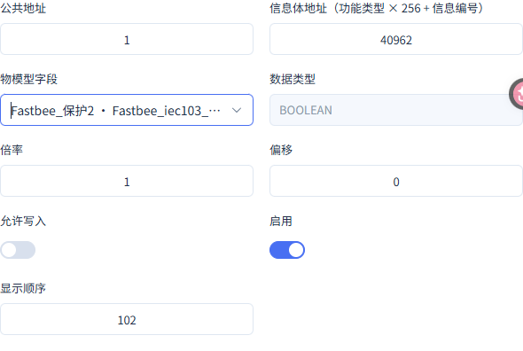
Common address 1, FUN160, INF2 correspond to 40962; this point is read-only.
Screenshot Highlights
| Field / Control | Description |
|---|---|
| Common Address | The station address of the protection device; keep the platform and the device consistent. Required · Fill in: Fill according to the implementation plan · Example: 1 |
| FUN and INF | FUN160, INF1 to 10 correspond to platform point addresses 40961 to 40970. Required · Fill in: Fill according to the implementation plan · Example: Platform address=FUN×256+INF |
| Point Mapping | All ten points are type BOOLEAN, scale 1, offset 0; only 40961 allows write. Required · Fill in: Fill according to the implementation plan · Example: BOOLEAN / 1 / 0 |
| Information Object Address | Used to complete "Configuring the Protection 2 Point". Required · Fill in: 40962 |
| Protection Point | Used to complete "Configuring the Protection 2 Point". Required · Fill in: FUN160 / INF2 |
| Write Permission | Used to complete "Configuring the Protection 2 Point". Required · Fill in: Read-only |
9. Configuring the Protection 3 Point
Location: IoT → Device Management → Product Management → Product Details → Device Protocol Configuration → Point Mapping Steps: Map information object address 40963 to Protection 3, with type BOOLEAN, scale 1, offset 0, and enable.
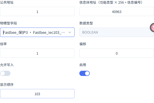
Common address 1, FUN160, INF3 correspond to 40963; this point is read-only.
Screenshot Highlights
| Field / Control | Description |
|---|---|
| Common Address | The station address of the protection device; keep the platform and the device consistent. Required · Fill in: Fill according to the implementation plan · Example: 1 |
| FUN and INF | FUN160, INF1 to 10 correspond to platform point addresses 40961 to 40970. Required · Fill in: Fill according to the implementation plan · Example: Platform address=FUN×256+INF |
| Point Mapping | All ten points are type BOOLEAN, scale 1, offset 0; only 40961 allows write. Required · Fill in: Fill according to the implementation plan · Example: BOOLEAN / 1 / 0 |
| Information Object Address | Used to complete "Configuring the Protection 3 Point". Required · Fill in: 40963 |
| Protection Point | Used to complete "Configuring the Protection 3 Point". Required · Fill in: FUN160 / INF3 |
| Write Permission | Used to complete "Configuring the Protection 3 Point". Required · Fill in: Read-only |
10. Configuring the Protection 4 Point
Location: IoT → Device Management → Product Management → Product Details → Device Protocol Configuration → Point Mapping Steps: Map information object address 40964 to Protection 4, with type BOOLEAN, scale 1, offset 0, and enable.
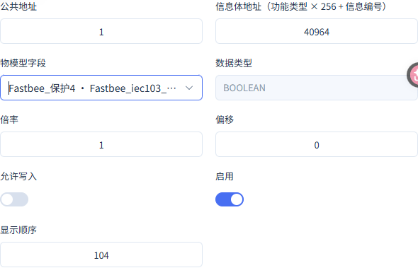
Common address 1, FUN160, INF4 correspond to 40964; this point is read-only.
Screenshot Highlights
| Field / Control | Description |
|---|---|
| Common Address | The station address of the protection device; keep the platform and the device consistent. Required · Fill in: Fill according to the implementation plan · Example: 1 |
| FUN and INF | FUN160, INF1 to 10 correspond to platform point addresses 40961 to 40970. Required · Fill in: Fill according to the implementation plan · Example: Platform address=FUN×256+INF |
| Point Mapping | All ten points are type BOOLEAN, scale 1, offset 0; only 40961 allows write. Required · Fill in: Fill according to the implementation plan · Example: BOOLEAN / 1 / 0 |
| Information Object Address | Used to complete "Configuring the Protection 4 Point". Required · Fill in: 40964 |
| Protection Point | Used to complete "Configuring the Protection 4 Point". Required · Fill in: FUN160 / INF4 |
| Write Permission | Used to complete "Configuring the Protection 4 Point". Required · Fill in: Read-only |
11. Configuring the Protection 5 Point
Location: IoT → Device Management → Product Management → Product Details → Device Protocol Configuration → Point Mapping Steps: Map information object address 40965 to Protection 5, with type BOOLEAN, scale 1, offset 0, and enable.
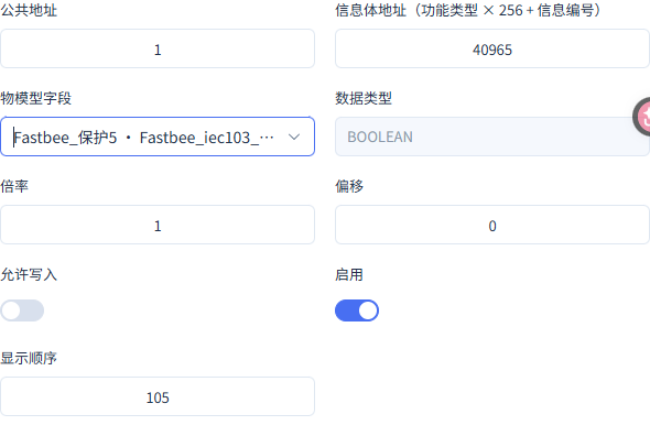
Common address 1, FUN160, INF5 correspond to 40965; this point is read-only.
Screenshot Highlights
| Field / Control | Description |
|---|---|
| Common Address | The station address of the protection device; keep the platform and the device consistent. Required · Fill in: Fill according to the implementation plan · Example: 1 |
| FUN and INF | FUN160, INF1 to 10 correspond to platform point addresses 40961 to 40970. Required · Fill in: Fill according to the implementation plan · Example: Platform address=FUN×256+INF |
| Point Mapping | All ten points are type BOOLEAN, scale 1, offset 0; only 40961 allows write. Required · Fill in: Fill according to the implementation plan · Example: BOOLEAN / 1 / 0 |
| Information Object Address | Used to complete "Configuring the Protection 5 Point". Required · Fill in: 40965 |
| Protection Point | Used to complete "Configuring the Protection 5 Point". Required · Fill in: FUN160 / INF5 |
| Write Permission | Used to complete "Configuring the Protection 5 Point". Required · Fill in: Read-only |
12. Configuring the Protection 6 Point
Location: IoT → Device Management → Product Management → Product Details → Device Protocol Configuration → Point Mapping Steps: Map information object address 40966 to Protection 6, with type BOOLEAN, scale 1, offset 0, and enable.
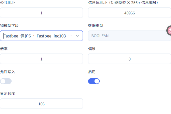
Common address 1, FUN160, INF6 correspond to 40966; this point is read-only.
Screenshot Highlights
| Field / Control | Description |
|---|---|
| Common Address | The station address of the protection device; keep the platform and the device consistent. Required · Fill in: Fill according to the implementation plan · Example: 1 |
| FUN and INF | FUN160, INF1 to 10 correspond to platform point addresses 40961 to 40970. Required · Fill in: Fill according to the implementation plan · Example: Platform address=FUN×256+INF |
| Point Mapping | All ten points are type BOOLEAN, scale 1, offset 0; only 40961 allows write. Required · Fill in: Fill according to the implementation plan · Example: BOOLEAN / 1 / 0 |
| Information Object Address | Used to complete "Configuring the Protection 6 Point". Required · Fill in: 40966 |
| Protection Point | Used to complete "Configuring the Protection 6 Point". Required · Fill in: FUN160 / INF6 |
| Write Permission | Used to complete "Configuring the Protection 6 Point". Required · Fill in: Read-only |
13. Configuring the Protection 7 Point
Location: IoT → Device Management → Product Management → Product Details → Device Protocol Configuration → Point Mapping Steps: Map information object address 40967 to Protection 7, with type BOOLEAN, scale 1, offset 0, and enable.
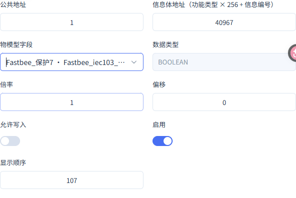
Common address 1, FUN160, INF7 correspond to 40967; this point is read-only.
Screenshot Highlights
| Field / Control | Description |
|---|---|
| Common Address | The station address of the protection device; keep the platform and the device consistent. Required · Fill in: Fill according to the implementation plan · Example: 1 |
| FUN and INF | FUN160, INF1 to 10 correspond to platform point addresses 40961 to 40970. Required · Fill in: Fill according to the implementation plan · Example: Platform address=FUN×256+INF |
| Point Mapping | All ten points are type BOOLEAN, scale 1, offset 0; only 40961 allows write. Required · Fill in: Fill according to the implementation plan · Example: BOOLEAN / 1 / 0 |
| Information Object Address | Used to complete "Configuring the Protection 7 Point". Required · Fill in: 40967 |
| Protection Point | Used to complete "Configuring the Protection 7 Point". Required · Fill in: FUN160 / INF7 |
| Write Permission | Used to complete "Configuring the Protection 7 Point". Required · Fill in: Read-only |
14. Configuring the Protection 8 Point
Location: IoT → Device Management → Product Management → Product Details → Device Protocol Configuration → Point Mapping Steps: Map information object address 40968 to Protection 8, with type BOOLEAN, scale 1, offset 0, and enable.
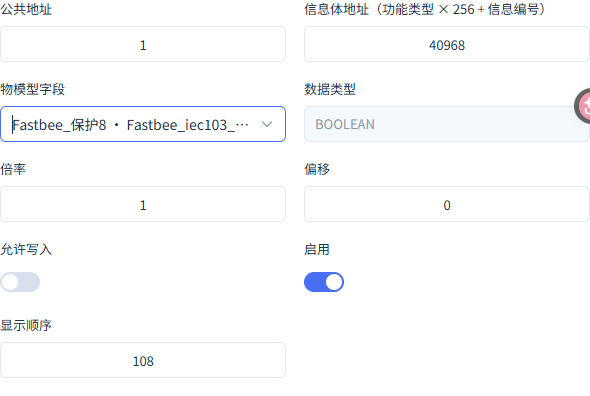
Common address 1, FUN160, INF8 correspond to 40968; this point is read-only.
Screenshot Highlights
| Field / Control | Description |
|---|---|
| Common Address | The station address of the protection device; keep the platform and the device consistent. Required · Fill in: Fill according to the implementation plan · Example: 1 |
| FUN and INF | FUN160, INF1 to 10 correspond to platform point addresses 40961 to 40970. Required · Fill in: Fill according to the implementation plan · Example: Platform address=FUN×256+INF |
| Point Mapping | All ten points are type BOOLEAN, scale 1, offset 0; only 40961 allows write. Required · Fill in: Fill according to the implementation plan · Example: BOOLEAN / 1 / 0 |
| Information Object Address | Used to complete "Configuring the Protection 8 Point". Required · Fill in: 40968 |
| Protection Point | Used to complete "Configuring the Protection 8 Point". Required · Fill in: FUN160 / INF8 |
| Write Permission | Used to complete "Configuring the Protection 8 Point". Required · Fill in: Read-only |
15. Configuring the Protection 9 Point
Location: IoT → Device Management → Product Management → Product Details → Device Protocol Configuration → Point Mapping Steps: Map information object address 40969 to Protection 9, with type BOOLEAN, scale 1, offset 0, and enable.
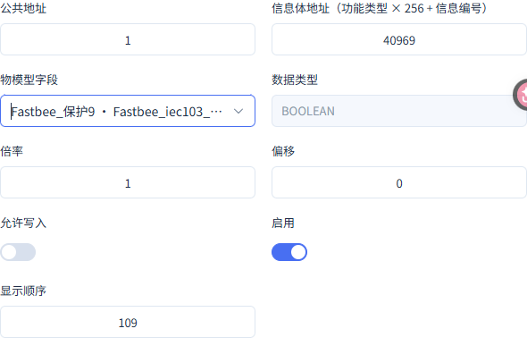
Common address 1, FUN160, INF9 correspond to 40969; this point is read-only.
Screenshot Highlights
| Field / Control | Description |
|---|---|
| Common Address | The station address of the protection device; keep the platform and the device consistent. Required · Fill in: Fill according to the implementation plan · Example: 1 |
| FUN and INF | FUN160, INF1 to 10 correspond to platform point addresses 40961 to 40970. Required · Fill in: Fill according to the implementation plan · Example: Platform address=FUN×256+INF |
| Point Mapping | All ten points are type BOOLEAN, scale 1, offset 0; only 40961 allows write. Required · Fill in: Fill according to the implementation plan · Example: BOOLEAN / 1 / 0 |
| Information Object Address | Used to complete "Configuring the Protection 9 Point". Required · Fill in: 40969 |
| Protection Point | Used to complete "Configuring the Protection 9 Point". Required · Fill in: FUN160 / INF9 |
| Write Permission | Used to complete "Configuring the Protection 9 Point". Required · Fill in: Read-only |
16. Configuring the Protection 10 Point
Location: IoT → Device Management → Product Management → Product Details → Device Protocol Configuration → Point Mapping Steps: Map information object address 40970 to Protection 10, with type BOOLEAN, scale 1, offset 0, and enable.
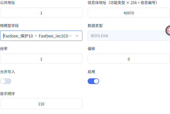
Common address 1, FUN160, INF10 correspond to 40970; this point is read-only.
Screenshot Highlights
| Field / Control | Description |
|---|---|
| Common Address | The station address of the protection device; keep the platform and the device consistent. Required · Fill in: Fill according to the implementation plan · Example: 1 |
| FUN and INF | FUN160, INF1 to 10 correspond to platform point addresses 40961 to 40970. Required · Fill in: Fill according to the implementation plan · Example: Platform address=FUN×256+INF |
| Point Mapping | All ten points are type BOOLEAN, scale 1, offset 0; only 40961 allows write. Required · Fill in: Fill according to the implementation plan · Example: BOOLEAN / 1 / 0 |
| Information Object Address | Used to complete "Configuring the Protection 10 Point". Required · Fill in: 40970 |
| Protection Point | Used to complete "Configuring the Protection 10 Point". Required · Fill in: FUN160 / INF10 |
| Write Permission | Used to complete "Configuring the Protection 10 Point". Required · Fill in: Read-only |
17. Saving the Single-Point Control Template
Location: IoT → Device Management → Product Management → Product Details → Device Protocol Configuration → Command Mapping Steps: Select CONTROL, with common address 1 and information object address 40961, associate Protection 1, and enable.
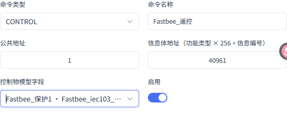
The CONTROL template uses the writable Protection 1 point address 40961.
Screenshot Highlights
| Field / Control | Description |
|---|---|
| Control Template | CONTROL, common address 1, 40961, associated with Protection 1 and enabled. Required · Fill in: Fill according to the implementation plan · Example: CONTROL / 1 / 40961 |
| Command Type | Used to complete "Saving the Single-Point Control Template". Required · Fill in: CONTROL |
| Station Address / Point Address | Used to complete "Saving the Single-Point Control Template". Required · Fill in: 1 / 40961 |
2. Verifying the TCP Gateway Session and Demo Point Table
The upper-half image shows the target endpoint and INF1 to 6, and the lower half shows INF5 to 10; together they verify all ten points. Initially odd false and even true.
18. Verifying TCP Gateway Connection Parameters and the Upper Half of the Point Table
Location: FMQX Web → Edit Point Table and Connection Steps: Open the configured session and verify the FMQ target Host, Port, TCP gateway combination, and link/common address.
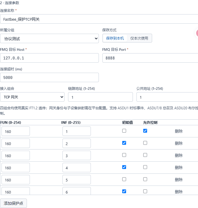
Target 127.0.0.1:8888, TCP gateway, link address 1, common address 1; the upper half shows INF1 to 6.
Screenshot Highlights
| Field / Control | Description |
|---|---|
| FMQ Target Host | The FMQ-reachable address the device actively connects to; the local-machine demo uses the loopback address. Required · Fill in: Fill according to the implementation plan · Example: 127.0.0.1 |
| FMQ Target Port | The TCP listening port of FMQ; keep consistent with the device target. Required · Fill in: Fill according to the implementation plan · Example: 8888 |
| Access Combination | Select TCP gateway; the device connects to FMQ over TCP. Required · Fill in: TCP网关 |
| Link Address | The FT1.2 link identifier; keep both ends consistent. Required · Fill in: Fill according to the implementation plan · Example: 1 |
| Common Address | The station address of the protection device; keep the platform and the device consistent. Required · Fill in: Fill according to the implementation plan · Example: 1 |
| Demo Point Table | Ten points FUN160/INF1 to 10, initially odd false and even true; only the first point allows control. Required · Fill in: Fill according to the implementation plan · Example: 160 / 1–10 |
| Target Host | Used to complete "Verifying TCP Gateway Connection Parameters and the Upper Half of the Point Table". Required · Fill in: 127.0.0.1 |
| Target Port | Used to complete "Verifying TCP Gateway Connection Parameters and the Upper Half of the Point Table". Required · Fill in: 8888 |
| Link Address / Common Address | Used to complete "Verifying TCP Gateway Connection Parameters and the Upper Half of the Point Table". Required · Fill in: 1 / 1 |
19. Verifying the Lower Half of the Demo Point Table
Location: FMQX Web → IEC103 Connection → Point Table Editing Steps: Scroll to the lower half of the point table and verify FUN160, INF5 to 10; for first-time configuration, complete all ten points and save.
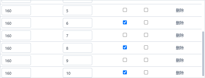
The upper and lower parts together cover INF1 to 10; initially odd false and even true, and only 160/1 allows control.
Screenshot Highlights
| Field / Control | Description |
|---|---|
| Demo Point Table | Ten points FUN160/INF1 to 10, initially odd false and even true; only the first point allows control. Required · Fill in: Fill according to the implementation plan · Example: 160 / 1–10 |
| Point Table | Used to complete "Verifying the Lower Half of the Demo Point Table". Required · Fill in: 160 / 1–10 |
| Initial Values | Used to complete "Verifying the Lower Half of the Demo Point Table". Required · Fill in: Odd false; even true |
20. Understanding the Link Status First-Frame Entry
Location: FMQX Web → IEC103 Protection Device Workspace Steps: Verify the workspace's TCP combination, link address 1, and common address 1; after connecting, Send Link Status First Frame becomes available.

The first-frame entry is greyed out while disconnected; TCP_GATEWAY, link 1, and common 1 remain visible. The first frame declares link status.
Screenshot Highlights
| Field / Control | Description |
|---|---|
| Access Combination | Select TCP gateway; the device connects to FMQ over TCP. Required · Fill in: Fill according to the implementation plan · Example: TCP网关 |
| Link Address | The FT1.2 link identifier; keep both ends consistent. Required · Fill in: Fill according to the implementation plan · Example: 1 |
| Common Address | The station address of the protection device; keep the platform and the device consistent. Required · Fill in: Fill according to the implementation plan · Example: 1 |
3. Saving an Independent General Interrogation Template
21. Saving the Complete General Interrogation Template
Location: IoT → Device Management → Product Management → Product Details → Device Protocol Configuration → Command Mapping Steps: Select GENERAL_INTERROGATION, fill in the name, common address 1, and information object address 40961, associate Protection 1, and enable.
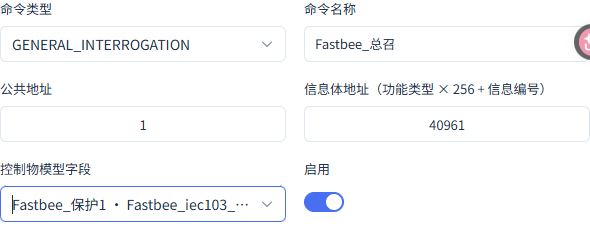
The general interrogation template has an explicit associated field; the native whole-station request uses FUN255, INF0.
Screenshot Highlights
| Field / Control | Description |
|---|---|
| Command Type | Used to complete "Saving the Complete General Interrogation Template". Required · Fill in: GENERAL_INTERROGATION |
| Common Address and Associated Point | Used to complete "Saving the Complete General Interrogation Template". Required · Fill in: 1 / 40961 |
4. Publishing and Connecting the Device
22. Publishing the Product Configuration
Location: Product Details → Basic Information → Publish Steps: Verify the current product, then click OK in the publish confirmation box.
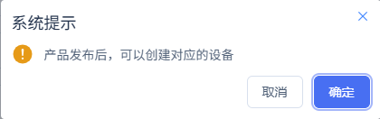
After the configuration is submitted, continue to view the application result on the target node.
23. Confirming the Configuration Has Been Applied
Location: Product Details → Sync Details Steps: Verify the target node is APPLIED, then connect the FMQX session.
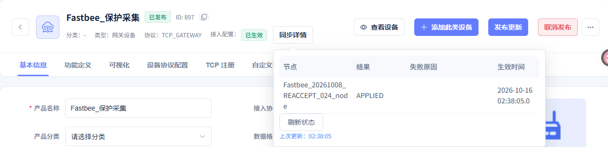
The configuration has been applied, effective at 2026-10-16 02:38:05.
5. Reporting Ten Different Addresses in Turn
The sample values are odd true and even false. When the right evidence panel covers the report button, collapse it first, then operate the corresponding row.
24. Reporting the First Protection Point
Location: FMQX Web → Communication → Protection Point Steps: Collapse the right evidence panel, select true on row 160/1, and click Report ASDU1 Once on that row.

The actual current value of 160/1 is true; the event dropdown selects the value to send.
Screenshot Highlights
| Field / Control | Description |
|---|---|
| Event Value to Send | Selects false or true for the next event; it does not represent the current actual value. Required · Fill in: Fill according to the implementation plan · Example: Odd true; even false |
| FUN / INF | Used to complete "Reporting the First Protection Point". Required · Fill in: 160 / 1 |
| Event Value | Used to complete "Reporting the First Protection Point". Required · Fill in: true / Closed |
25. Reporting Ten Different Addresses in Turn
Location: FMQX Web → Communication → Protection Point Steps: After completing the 160/1 report, continue sending once for each of INF2 to 10; select true for odd and false for even, waiting for the platform to update before operating the next point — ten addresses in total, once each.

The ten samples correspond to 40961 to 40970 respectively; the final actual current value of 160/10 is false.
Screenshot Highlights
| Field / Control | Description |
|---|---|
| Event Value to Send | Selects false or true for the next event; it does not represent the current actual value. Required · Fill in: Fill according to the implementation plan · Example: Odd true; even false |
| FUN and INF | FUN160, INF1 to 10 correspond to platform point addresses 40961 to 40970. Required · Fill in: Fill according to the implementation plan · Example: Platform address=FUN×256+INF |
| FUN / INF | Used to complete "Reporting Ten Different Addresses in Turn". Required · Fill in: 160 / 1–10 |
| Ten-Point Sample Values | Used to complete "Reporting Ten Different Addresses in Turn". Required · Fill in: true, false, true, false, true, false, true, false, true, false |
6. First Control and Independent State Report
The request ASDU20/COT20 and the feedback ASDU1/COT12 are associated by the same RII. The actual current value column and the to-send event dropdown are read separately.
26. Changing Protection 1 to Open from the Platform
Location: Device Details → Running Status → Protection 1 Steps: Verify Protection 1 is currently Closed, set the target to false, and send once.
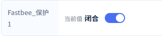
Protection 1 was Closed before control; this target is false, Open.
Screenshot Highlights
| Field / Control | Description |
|---|---|
| First Protection 1 Control | Closed before writing, target false, Open. Required · Fill in: Fill according to the implementation plan · Example: 160 / 1=false |
| Control Point | Used to complete "Changing Protection 1 to Open from the Platform". Required · Fill in: 160 / 1 (40961) |
| Target Value | Used to complete "Changing Protection 1 to Open from the Platform". Required · Fill in: false / Open |
27. Verifying the First Native Control Request
Location: FMQX Web → Communication Records → Raw Frames Steps: Open the 02:38:27.118 received frame and verify the ASDU, cause code, FUN/INF, and target value.
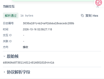
ASDU20, COT20, 160/1 target false, RII is 4.
28. Reading the Device's Actual Current Value
Location: FMQX Web → Communication → Protection Point 160/1 Steps: Read the actual current value column of 160/1.

The actual current value has changed to false; the to-send event on the right can still stay true — read the two separately.
Screenshot Highlights
| Field / Control | Description |
|---|---|
| Event Value to Send | Selects false or true for the next event; it does not represent the current actual value. Required · Fill in: Fill according to the implementation plan · Example: Odd true; even false |
29. Verifying the First Native Execution Feedback
Location: FMQX Web → Communication Records → Raw Frames Steps: View the 02:38:27.120 sent frame and associate it with the original request by RII.
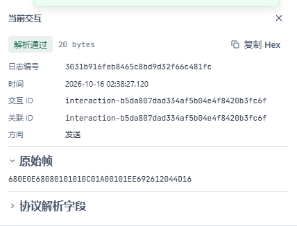
ASDU1, COT12, 160/1=false, with the same RII 4.
30. Independently Reporting the State After the First Control
Location: FMQX Web → Protection Point 160/1 and Communication Records Steps: Collapse the evidence panel, select false on row 160/1 and report once; do not save the point table configuration, then view the new sent frame.
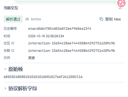
The 02:38:28.534 ASDU1, COT1 independent event is false, later than the first execution feedback.
Screenshot Highlights
| Field / Control | Description |
|---|---|
| Independent Event | Used to complete "Independently Reporting the State After the First Control". Required · Fill in: 160 / 1=false |
7. Manually Reconnecting After a Normal Disconnect
A normal reconnection reuses the published configuration; after recovery, another new event 160/2=true is sent, verified separately from the Protection 1 control.
31. Disconnecting the Session Normally
Location: FMQX Web → This Article's Session Steps: Click Disconnect and verify the left side of the session shows Disconnected.

The same TCP session is disconnected; the connection target is still 127.0.0.1:8888.
Screenshot Highlights
| Field / Control | Description |
|---|---|
| FMQ Target Host | The FMQ-reachable address the device actively connects to; the local-machine demo uses the loopback address. Required · Fill in: Fill according to the implementation plan · Example: 127.0.0.1 |
| FMQ Target Port | The TCP listening port of FMQ; keep consistent with the device target. Required · Fill in: Fill according to the implementation plan · Example: 8888 |
32. Manually Connecting the Original Session
Location: FMQX Web → This Article's Session Steps: Click Connect and verify the left side of the same session shows Connected.

The manual reconnection is complete; this stage reuses the published configuration.
8. Controlling to Closed After Recovery
Continue using the Protection 1 control entry above, with the target changed to true; the RII is matched by this request and feedback — do not fill in fixed protocol constants.
33. Controlling Protection 1 After Recovery and Verifying the New Request
Location: FMQX Web → Communication Records → Raw Frames Steps: Reuse the Protection 1 control entry, set the target to true and send once, then verify the 02:38:39.981 received frame.
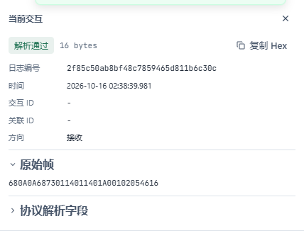
ASDU20, COT20, 160/1 target true, RII is 5.
Screenshot Highlights
| Field / Control | Description |
|---|---|
| Post-recovery Protection 1 Control | Open before writing, target true, Closed. Required · Fill in: Fill according to the implementation plan · Example: 160 / 1=true |
| Control Point | Used to complete "Controlling Protection 1 After Recovery and Verifying the New Request". Required · Fill in: 160 / 1 (40961) |
| Target Value | Used to complete "Controlling Protection 1 After Recovery and Verifying the New Request". Required · Fill in: true / Closed |
34. Reading the Actual Current Value After Recovery
Location: FMQX Web → Communication → Protection Point 160/1 Steps: Read the actual current value column of 160/1.

The actual current value has changed to true; the to-send event dropdown can still stay false.
Screenshot Highlights
| Field / Control | Description |
|---|---|
| Event Value to Send | Selects false or true for the next event; it does not represent the current actual value. Required · Fill in: Fill according to the implementation plan · Example: Odd true; even false |
35. Verifying the Second Native Execution Feedback
Location: FMQX Web → Communication Records → Raw Frames Steps: View the 02:38:39.982 sent frame and verify the target and the matching RII.
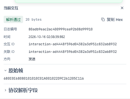
ASDU1, COT12, 160/1=true, with the same RII 5.
36. Independently Reporting the State After the Second Control
Location: FMQX Web → Protection Point 160/1 and Communication Records Steps: Collapse the evidence panel, select true on row 160/1 and report once; do not save the point table configuration, then view the new sent frame.
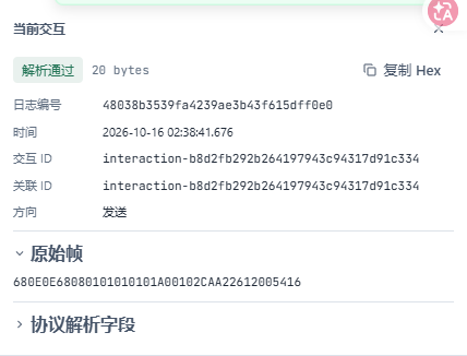
The 02:38:41.676 ASDU1, COT1 independent event is true, later than the second execution feedback.
Screenshot Highlights
| Field / Control | Description |
|---|---|
| Independent Event | Used to complete "Independently Reporting the State After the Second Control". Required · Fill in: 160 / 1=true |
9. Pausing the Single-Point Control Phase
37. Pausing the Publish to End the Single-Point Control Demo
Location: Product Details → Unpublish Steps: Read the notice that republishing may reset data, verify the product, then click OK.
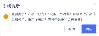
Stop the single-point control phase first, then prepare the general interrogation separately.
38. Confirming the Paused Configuration Has Been Applied
Location: Product Details → Sync Details Steps: Verify the target node after unpublish is APPLIED.
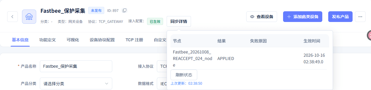
The unpublish has been applied, effective at 2026-10-16 02:38:49.
10. Reading the Whole-Station State After Republishing
Saving the connection configuration re-initializes the demo point table. Before the general interrogation, read the current ten points first — in this example odd false and even true; this set of values is separate from the earlier samples and the state after the second control.
The general interrogation request is ASDU7/COT9; after the ten-point return, it ends with ASDU8/COT10, associated by the same SIN.
39. Restoring the Publish and Reading Point Values Before the General Interrogation
Location: Product Details → Publish and Sync Details; FMQX Web → This Article's Session Steps: Restore the original product via the publish entry above, wait for APPLIED, then connect the original session; verify the current point table before initiating the general interrogation.
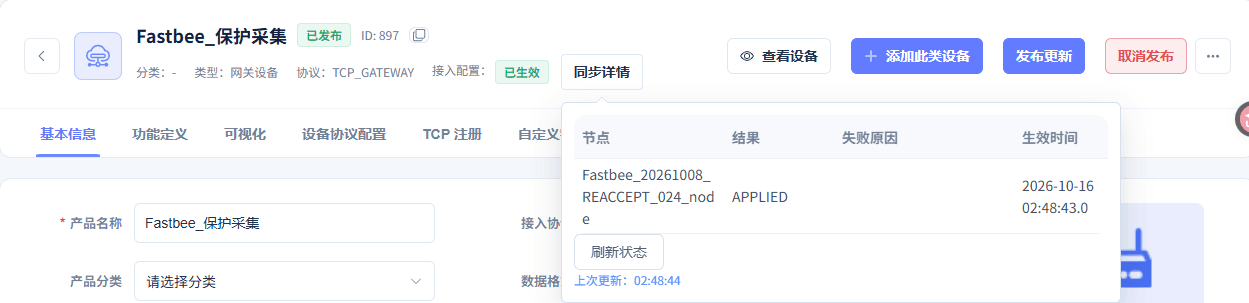
The general interrogation phase configuration has been applied, effective at 2026-10-16 02:48:43.
40. Initiating a Station-Wide General Interrogation from the Platform
Location: Device Details → Running Status → General Interrogation Steps: Select the general interrogation template for station address 1 and click Initiate General Interrogation.

The platform uses the published general interrogation template to read the station's ten-point states.
Screenshot Highlights
| Field / Control | Description |
|---|---|
| General Interrogation Template | Used to complete "Initiating a Station-Wide General Interrogation from the Platform". Required · Fill in: FastBee_总召 · Station address 1 |
41. Verifying the Native General Interrogation Request
Location: FMQX Web → Communication Records → Raw Frames Steps: View the native general interrogation frame received at 02:48:52.776.
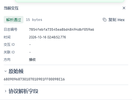
ASDU7, COT9, FUN255, INF0, SIN is 9.
42. Verifying the Native General Interrogation End
Location: FMQX Web → Communication Records → Raw Frames Steps: Verify the 02:48:52.782 end frame after the ten-point return.
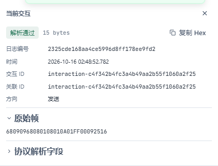
ASDU8, COT10, FUN255, INF0, with the same SIN 9, matching the request.
43. Reading the Platform General Interrogation Feedback
Location: Device Details → Running Status → General Interrogation Steps: View the platform feedback after the general interrogation operation.

The device general interrogation end has been confirmed; please verify the data collected this time.
11. Filtering and Refreshing the Three History Windows Separately
The ten samples show ten rows, and the Protection 1 control shows four rows; the general interrogation's ten fields within the same second merge into one row. A blank column means the row does not have the corresponding field.
44. Filling in the Complete Time Range for the Ten-Point Samples
Location: Data Center → Historical Data Steps: Fill in the complete start and end date-times.
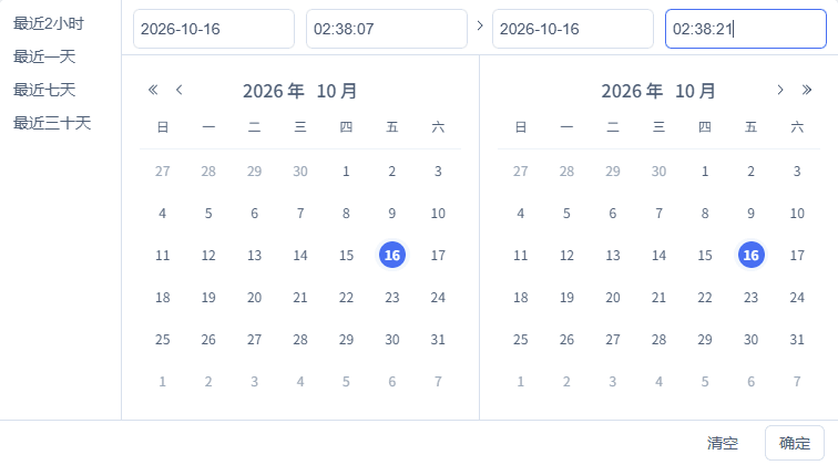
Query the corresponding operation records by complete date-time.
Screenshot Highlights
| Field / Control | Description |
|---|---|
| Start Time | Used to complete "Filling in the Complete Time Range for the Ten-Point Samples". Required · Fill in: 2026-10-16 02:38:07 |
| End Time | Used to complete "Filling in the Complete Time Range for the Ten-Point Samples". Required · Fill in: 2026-10-16 02:38:21 |
45. Filtering the Ten-Point Sample Fields
Location: Data Center → Historical Data Steps: Select this device and Protection 1 to 10, verify the time conditions, then click Query.

This device, the fields, and the complete time range stay consistent.
Screenshot Highlights
| Field / Control | Description |
|---|---|
| Fields | Used to complete "Filtering the Ten-Point Sample Fields". Required · Fill in: Protection 1–10 |
46. Refreshing the Ten-Point Sample History
Location: Data Center → Historical Data Steps: Keep the device, fields, and time conditions, and click the refresh button at the top right of the result area.

After refresh, the ten-address samples show 10 rows.
47. Verifying the Ten-Point Sample History Item by Item
Location: Data Center → Historical Data → Query Results Steps: Verify Protection 1 to 10 row by row, by time and field.
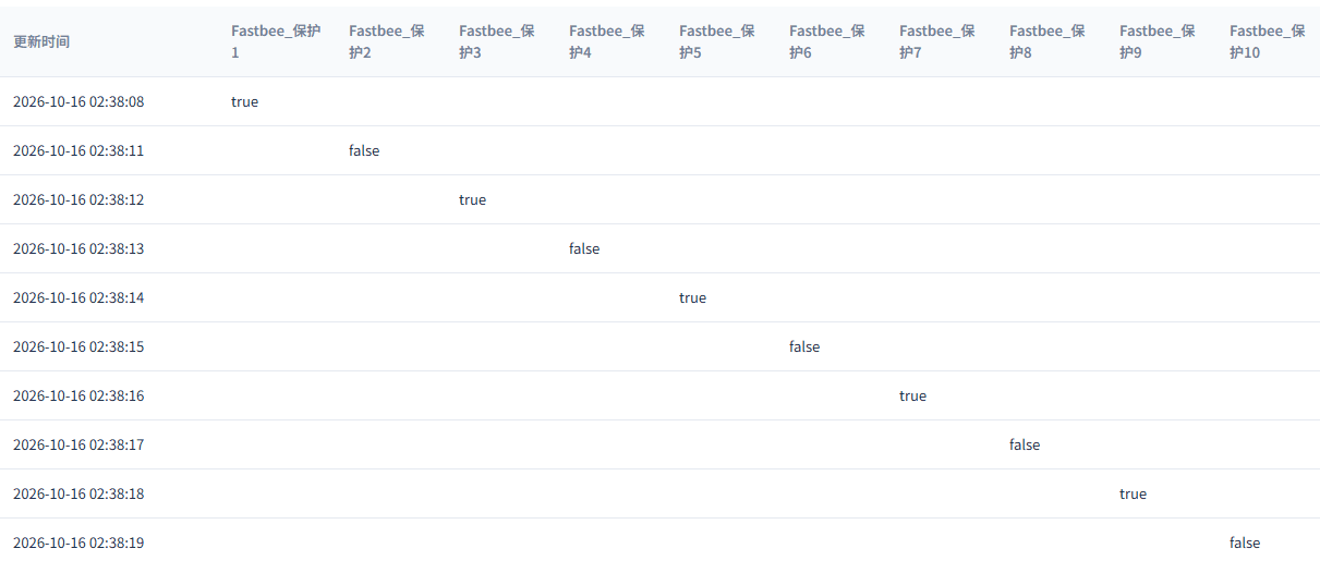
02:38:08, 11, 12, 13, 14, 15, 16, 17, 18, 19 correspond to Protection 1 to 10 in order, odd true and even false; a blank column means the row does not have that field.
48. Filling in the Complete Time Range for the Protection 1 Control
Location: Data Center → Historical Data Steps: Fill in the complete start and end date-times.
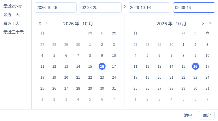
Query the corresponding operation records by complete date-time.
Screenshot Highlights
| Field / Control | Description |
|---|---|
| Start Time | Used to complete "Filling in the Complete Time Range for the Protection 1 Control". Required · Fill in: 2026-10-16 02:38:25 |
| End Time | Used to complete "Filling in the Complete Time Range for the Protection 1 Control". Required · Fill in: 2026-10-16 02:38:43 |
49. Filtering the Protection 1 Control Field
Location: Data Center → Historical Data Steps: Select this device and Protection 1, verify the time conditions, then click Query.

This device, the fields, and the complete time range stay consistent.
Screenshot Highlights
| Field / Control | Description |
|---|---|
| Fields | Used to complete "Filtering the Protection 1 Control Field". Required · Fill in: Protection 1 |
50. Refreshing the Protection 1 Control History
Location: Data Center → Historical Data Steps: Keep the device, fields, and time conditions, and click the refresh button at the top right of the result area.

After refresh, Protection 1 shows 4 rows of records.
51. Verifying the Protection 1 Control History Item by Item
Location: Data Center → Historical Data → Query Results Steps: Read the four rows of Protection 1 states by time, distinguishing execution feedback from independent events.

02:38:27=false, 02:38:28=false, 02:38:39=true, 02:38:41=true; each of the two feedbacks is followed by an independent event.
52. Filling in the Complete Time Range for the General Interrogation Ten Points
Location: Data Center → Historical Data Steps: Fill in the complete start and end date-times.
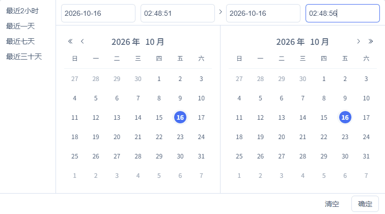
Query the corresponding operation records by complete date-time.
Screenshot Highlights
| Field / Control | Description |
|---|---|
| Start Time | Used to complete "Filling in the Complete Time Range for the General Interrogation Ten Points". Required · Fill in: 2026-10-16 02:48:51 |
| End Time | Used to complete "Filling in the Complete Time Range for the General Interrogation Ten Points". Required · Fill in: 2026-10-16 02:48:56 |
53. Filtering the General Interrogation Ten-Point Fields
Location: Data Center → Historical Data Steps: Select this device and Protection 1 to 10, verify the time conditions, then click Query.

This device, the fields, and the complete time range stay consistent.
Screenshot Highlights
| Field / Control | Description |
|---|---|
| Fields | Used to complete "Filtering the General Interrogation Ten-Point Fields". Required · Fill in: Protection 1–10 |
54. Refreshing the General Interrogation Ten-Point History
Location: Data Center → Historical Data Steps: Keep the device, fields, and time conditions, and click the refresh button at the top right of the result area.

After refresh, 1 row is shown, containing the complete ten fields.
55. Verifying the General Interrogation Ten-Point History Item by Item
Location: Data Center → Historical Data → Query Results Steps: Read the ten protection point fields of the 02:48:52 row.

The general interrogation ten points are odd false and even true, consistent with the point table re-initialized after saving the connection configuration.
12. Stopping and Viewing the Retained State
At the end, disconnect and turn off auto sending, auto reply, and auto reconnect, and deactivate the product publish entry. The initial point table after saving the configuration is verified separately from the platform current values and history.
56. Ending Send/Receive and Preserving the Session
Location: FMQX Web → This Article's Session Steps: Disconnect the session and confirm scheduled sending, auto reply, and Auto Reconnect are off.

The same protection TCP gateway session is disconnected; the target is still 127.0.0.1:8888.
Screenshot Highlights
| Field / Control | Description |
|---|---|
| Auto Reconnect | Turn off and save for long-term deactivation; saving re-initializes the demo session. Required · Fill in: Fill according to the implementation plan · Example: Turn off at the end |
57. Final Unpublish and Confirmation of Application
Location: Product Details → Unpublish and Sync Details Steps: Deactivate the product via the unpublish entry above, wait for application, then verify the sync details.
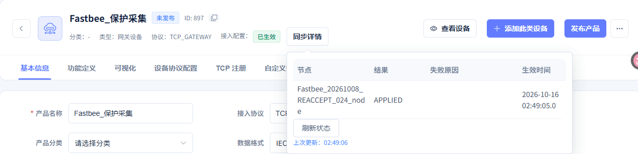
The final unpublish has been applied, effective at 2026-10-16 02:49:05.
58. Viewing the Ten-Point Current Values Retained After Stopping
Location: Device Details → Running Status → Real-time Metrics Steps: Read the ten protection points shown by the platform after stopping, item by item.
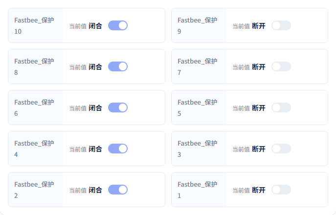
All ten points are fully visible: odd Open, even Closed.
Parameter Sources and Filling Reference
Product and Ten-Point Model
| Field / Control | How to Fill |
|---|---|
| Product Name | Holds this device's ten boolean models. Required · Fill in: 保护装置演示 |
| Device Number | Keep identical to the protocol-bound clientId. Required · Fill in: FastBee_IEC103TCPGW_Tutorial_01 |
| Model English Name | The English name is required; fill it in before saving the permission settings. Required · Fill in: Protection1 |
| Permission and History | Only Protection 1 is writable; all ten points have history enabled; true is Closed, false is Open. Required · Fill in: Protection 1 writable; history on for all ten pointsPublish after changes. |
| Product Type | Select Gateway Device to match the TCP gateway combination later. Required · Fill in: 网关设备网关设备: Manages gateway link access; pairs with the TCP_GATEWAY recipe. |
| Product Category | Optional by business classification; it does not replace the protocol selection. Required · Fill in: 未分类 |
| Firmware Version | Optional according to the actual situation; this example does not perform an upgrade. Required · Fill in: Optional |
| Network Access Method | Records the device's network access method; it does not change TCP protocol transport. Required · Fill in: WIFI |
| Device Authorization Code | Selected by product access rules; off in this example. Required · Fill in: 关闭关闭: Uses the existing access method; does not additionally enable the product authorization code.开启: Adds an authorization code requirement; the device must match the corresponding authorization. |
| Model Name and Identifier | Each point is an independent property; the model English translation is required and still needs to be completed in the image. Required · Fill in: 保护1 / Protection1 |
| Device Shadow | Off in this example; control requires the device to be truly online. Required · Fill in: 关闭关闭: Handled according to the real device online state; this example uses this option.开启: Enables retained-state-related processing; requires separate configuration and verification. |
Protocol Binding, Point Mapping, and Publish
| Field / Control | How to Fill |
|---|---|
| Data Format and Transport | The platform gateway device selects the native IEC103 and TCP_GATEWAY recipe. Required · Fill in: IEC 60870-5-103 / TCP_GATEWAYPublish after changes.IEC 60870-5-103 / TCP_GATEWAY: The control-plane gateway recipe; operation connects to FMQ over TCP and processes native frames by this device's binding and FUN/INF. |
| Device Binding | Bind the same gateway protection device; the device identifier matches this device's number. Required · Fill in: Device number identical to clientIdPublish after changes. |
| Link Address | The FT1.2 link identifier; keep both ends consistent. Required · Fill in: 1Reconnect after changes. |
| Common Address | The station address of the protection device; keep the platform and the device consistent. Required · Fill in: 1Reconnect after changes. |
| FUN and INF | FUN160, INF1 to 10 correspond to platform point addresses 40961 to 40970. Required · Fill in: Platform address=FUN×256+INF |
| Point Mapping | All ten points are type BOOLEAN, scale 1, offset 0; only 40961 allows write. Required · Fill in: BOOLEAN / 1 / 0Publish after changes. |
| Control Template | CONTROL, common address 1, 40961, associated with Protection 1 and enabled. Required · Fill in: CONTROL / 1 / 40961Publish after changes. |
| Publish and Application | After publishing or unpublishing, view the target node's APPLIED status. |
FMQX Web TCP Protection Device
| Field / Control | How to Fill |
|---|---|
| FMQ Target Host | The FMQ-reachable address the device actively connects to; the local-machine demo uses the loopback address. Required · Fill in: 127.0.0.1Reconnect after changes. |
| FMQ Target Port | The TCP listening port of FMQ; keep consistent with the device target. Required · Fill in: 8888Reconnect after changes. |
| Access Combination | Select TCP gateway; the device connects to FMQ over TCP. Required · Fill in: TCP网关Reconnect after changes.TCP网关: Accesses with the gateway combination as a TCP client; keep consistent with the control-plane TCP_GATEWAY recipe. |
| Demo Point Table | Ten points FUN160/INF1 to 10, initially odd false and even true; only the first point allows control. Required · Fill in: 160 / 1–10 |
| Link Status First Frame | The entry is available after connecting; it declares link status and cannot replace native execution feedback. |
| Connection and Recovery | Connect after the product is applied; manually reconnect the same session after a normal disconnect. Reconnect after changes. |
| Auto Reconnect | Turn off and save for long-term deactivation; saving re-initializes the demo session. Required · Fill in: Turn off at the end关闭: Does not connect automatically after disconnect; stays deactivated and requires manual connection.开启: Retries at intervals after the connection is interrupted; keeps trying to establish the connection. |
Point Events and Raw Frames
| Field / Control | How to Fill |
|---|---|
| Actual Current Value | Read the actual current column or the platform current value; read it separately from the to-send event on the right. |
| Event Value to Send | Selects false or true for the next event; it does not represent the current actual value. Required · Fill in: Odd true; even falsefalse: An Open-state event; sends this row's Open state.true: A Closed-state event; sends this row's Closed state. |
| Report ASDU1 Once | Collapse the evidence panel, then click the button on the corresponding row to report point by point. |
| Complete Raw Frame | Verify the complete HEX by direction, time, ASDU, cause code, FUN/INF, and RII or SIN. |
| Independent Event After Control | After control, select the corresponding value and report once, without saving the point table to overwrite the execution result. |
Platform Control and General Interrogation
| Field / Control | How to Fill |
|---|---|
| First Protection 1 Control | Closed before writing, target false, Open. Required · Fill in: 160 / 1=false |
| Post-recovery Protection 1 Control | Open before writing, target true, Closed. Required · Fill in: 160 / 1=true |
| Native Execution Feedback | The ASDU20/COT20 request and the ASDU1/COT12 feedback are associated by the same RII, followed by a separate COT1 event. |
| General Interrogation Template and End | Use the published general interrogation template; verify by the ASDU7 request, the ten-point return, the ASDU8 end, and the same SIN. Publish after changes. |
| Stop and Preserve | After disconnecting, stop scheduled sending and auto-reply; turn off auto reconnect and save, then deactivate the publish entry. Reconnect after changes. |
Three History Query Windows
| Field / Control | How to Fill |
|---|---|
| Device and Field Filtering | Select Protection 1 to 10 for the ten samples and the general interrogation; select only Protection 1 for the control. |
| Complete Time Range | Fill in complete date-times per operation to avoid mixing in other records. |
| History Values and Merged Rows | Different fields within the same second may merge into one row; blank means the row does not have that field. |
| Refresh Results | Keep the device, fields, and time conditions, and click refresh at the top right of the result area. |
FAQ and Recovery Methods
| Symptom | Possible Cause | Where to Check First | How to Recover |
|---|---|---|---|
| Session cannot connect | The FMQ listener or target endpoint does not match | Verify FMQ 8888, the product APPLIED status, and the TCP gateway combination | After fixing, connect the same session and send a new event first. |
| Point states do not correspond | The address or property mapping is inconsistent | Verify common 1, link 1, FUN160, and INF1 to 10 | Send only one known point, confirm the corresponding property, then continue. |
| The model cannot be saved | Required fields such as the English translation are not filled in completely | Verify the model name, English translation, and identifier | Complete the required fields and clear the validation prompts before saving. |
| The event dropdown differs from the actual value | The dropdown represents the next event to send | Read the actual current value column and the feedback with the matching RII | Select the corresponding value for the independent report; do not save the point table to overwrite the execution result. |
| Point values change after saving | The demo session is re-initialized from the initial point table | Re-read the current ten points before the general interrogation | Verify the new general interrogation against the current baseline; avoid applying values from after earlier controls. |
| The general interrogation has only one history row | Different fields within the same second are merged for display | Read the complete ten fields of that row | Verify column by column; do not equate blanks or row counts directly with point counts. |