


3D Scenes, Objects, and Layout
Scene properties control the background, lighting, and view of the entire scene. Node properties affect only the selected model or object. In Campus Spatial Monitoring, use Offices and R&D to compare the object list with the viewport.
1. Before You Start
| Item | Details |
|---|---|
| Entry point | Visualization → SCADA Management → 3D Scenes → Edit |
| Permissions | Access the scene editor. Make changes only in a project you are allowed to edit. |
| What to check | Model scale, the area to show, and what viewers should see first in preview |
2. Inspect Scene Properties and the Camera
- With no node selected, open Properties on the right to see scene settings. Check Scene Units before inspecting the grid, background, ambient light, and directional light. Do not use node scaling to mask a scene-wide scale problem.
- Under Initial Camera, check the camera type, position, and look-at target. When changing the initial view in your own project, use Apply Camera Settings and preview the scene to confirm the overview is not clipped.
- Use Reset Camera to return to the baseline view. Follow Theme affects the editor only. Use Scene Colors to inspect the scene's background, grid, and fog colors.
3. Locate a Node in the Object List
- Use Search Nodes in the left object list to find and select Offices and R&D. The right panel title and the bottom status bar should show the selected node.
- Under Properties → Spatial Transform, inspect position, rotation, and scale separately. To adjust only a label, use its offset under Annotation instead of moving the model.
- Check Visible, Locked, and Show Annotation. If an object is missing, verify visibility, whether its label is enabled, and the camera angle before considering recreating it.
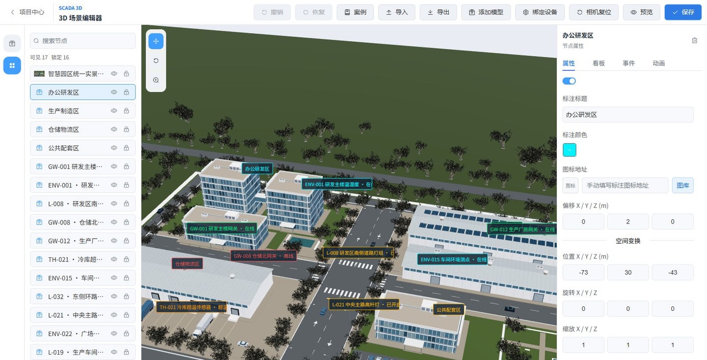
Follow the screenshot: Select Office and R&D Area on the left, confirm that the Properties panel on the right shows the same name, then scroll down to Spatial Transform. The node position shown is (-73, 30, -43) m, while the label offset is (0, 2, 0) m. Position places the node; offset only shifts the label relative to it. To raise a label, check the offset before moving the model.
4. Check the Result
In preview, the base model should be distinguishable from area markers, and labels should remain legible from typical viewpoints. Verify one area before adding more nodes and device data.