

Modbus access cases
提示
Modbus devices can be connected through cloud polling or an edge gateway.
1. Cloud polling
Why cloud polling is needed
Common DTUs and communication modules usually provide only MQTT or TCP transparent transmission. If a device uses the Modbus protocol and no edge gateway is added, the device data is not actively reported with enough platform-side context.
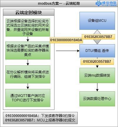
In this mode, FastBee builds Modbus read commands according to the collection-point template of the product, sends the commands to the target device, and performs polling from the cloud.
Because a reported Modbus RTU frame does not include an explicit platform register marker, the platform needs to mark and match the request and response. The current implementation uses a Redis lock on the polling thread and waits for the device response.

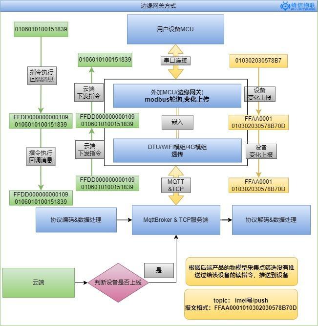
The overall implementation is shown below:
Modbus protocol decoding and encoding
1. Platform code
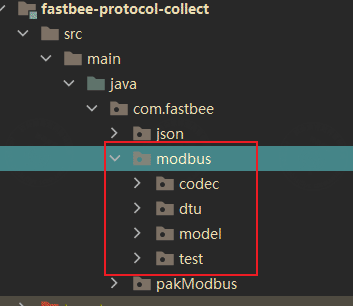
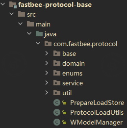
In the FastBee backend, Modbus message decoding and encoding are implemented in the location shown below:
2. Annotation-based decoding and encoding
FastBee provides a base package for annotation-based message decoding and encoding. It can be used to parse and generate many types of hardware messages, reducing repetitive backend development work.
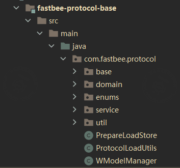
The following example shows how the wrapped Modbus protocol is decoded and encoded with annotations.
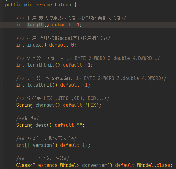
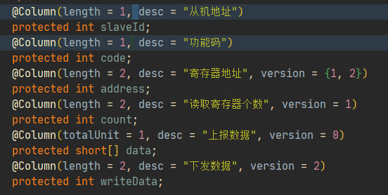
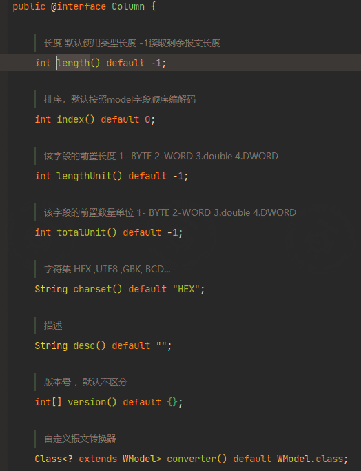
First, check the field definition of the @Column annotation:
length: specifies the field length.version: distinguishes downstream messages from upstream messages.totalUnit: specifies the preceding quantity unit of the field, which is used when parsing batch-read responses.
If you do not need to understand the frame parsing details, you can skip this section.
Key parsing rules:
int: used here to represent a one-byte message length. In Java,intis four bytes, but this parser treats the field according to the configured message length.totalUnit: indicates the quantity field before the current field. For example, whentotalUnit = 1, if the data length isn, the data list length isBYTE[2 * n].version: controls which command type a field participates in.
// When version is configured, the field is decoded or encoded only when the condition matches.
// When version is not configured, the field participates in all decoding and encoding.
//
// version = 0: parsed when the device reports data.
// version = 1: parsed when reading registers.
// version = 2: parsed when writing a single holding register.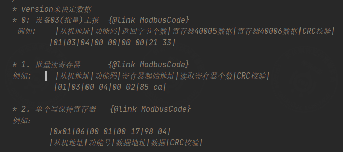
3. Backend cloud-polling implementation
The backend implements Modbus polling through scheduled tasks.
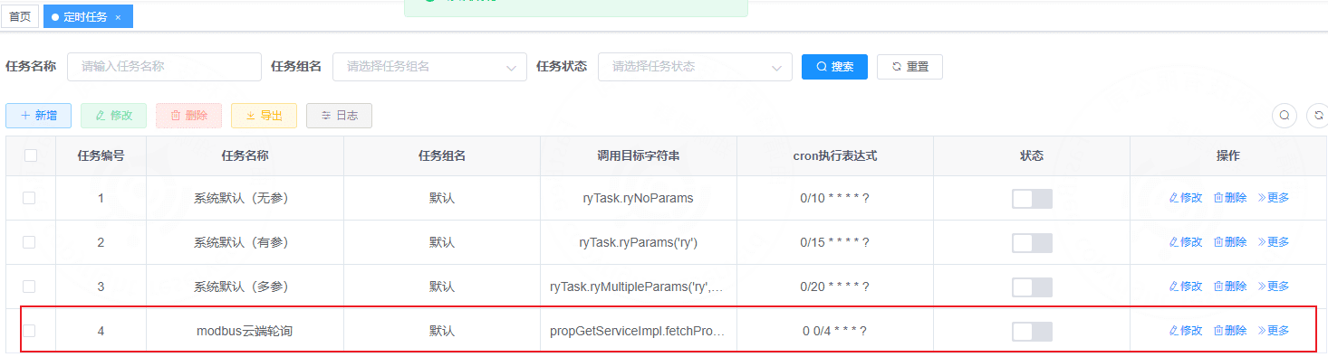
The backend entry point for Modbus cloud polling is shown below:
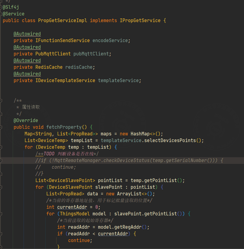
Processing flow:
- Filter online gateway devices.
- Read collection points from the product definition.
- Batch-generate and deliver Modbus read commands.
- Use a thread pool so that all commands for one sub-device are delivered in the same child thread.
- Use Redis as both the thread lock and the register marker.
- For each sub-device, the thread continues polling until the Redis cache expires or the device response is received, then sends the next command.
For implementation details, refer to the backend source code.
2. Edge gateway
提示
The edge gateway is used together with real-time cloud collection.
2.1 Solution overview
Because of the Modbus protocol characteristics, a raw Modbus frame reported to the cloud does not contain an address marker that the platform can directly use to identify the corresponding thing-model collection point.
To improve collection efficiency, real-time reporting, and general compatibility, this solution adds an MCU module as an edge gateway.
Hardware composition:
- The user's own device or MCU.
- A DTU or communication module in transparent transmission mode.
- An additional low-cost MCU that performs Modbus polling and reports changed values.
2.2 Message data
To solve the missing register-address marker in raw Modbus frames, the additional MCU wraps the Modbus protocol with an extra frame.
Device active reporting
FFAA              Wrapped frame header, used to ensure message integrity.
0D                Wrapped frame tail, used to ensure message integrity.
0001              Register address, used to identify the message.
010302030578B7    Raw Modbus frame.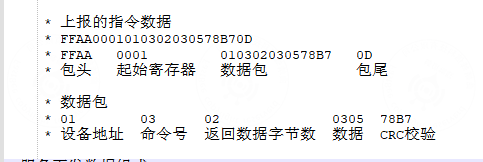
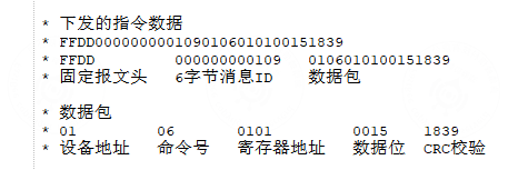
Service delivery
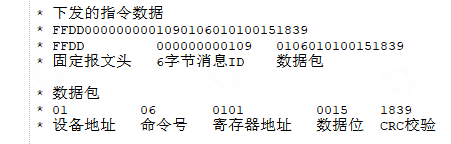
Device acknowledgement for service delivery
After a Modbus device receives and executes a write command, it reports the write command back to the platform to indicate that the command was executed successfully.
2.3 Overall process
2.4 Platform code
In the FastBee backend, decoding and encoding of the wrapped Modbus frame are implemented in the location shown below:
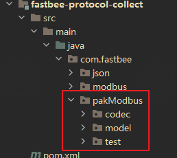
Annotation-based decoding and encoding
FastBee uses the same annotation-based decoding and encoding package for this wrapped protocol.
The wrapped Modbus protocol can also be defined through @Column. The key fields are:
length: specifies the field length.version: distinguishes downstream messages from upstream messages.totalUnit: specifies the preceding quantity unit of the field, which is used when parsing batch-read responses.
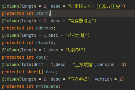
The message definition follows these rules:
- Java primitive numeric types do not distinguish signed and unsigned values at the type level in this parser.
intcan be used for a configured byte length. In the example,FFDDis two bytes andlength = 2, so the field is parsed as two bytes.shortrepresents two bytes. Modbus data fields are composed of two-byte values, soshort[]is used to support both single-value and batch-value parsing.totalUnitindicates the quantity field before the current field. For example, whentotalUnit = 1, if the data length isn, the data list length isBYTE[2 * n].
Annotation decoding and encoding test
The backend test class is PakModbusTest.
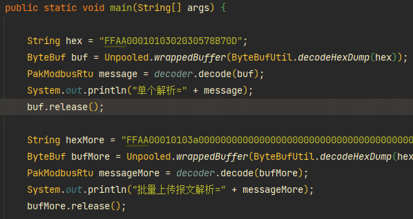
Example parsing results:
Single report parsing =
Read holding register (byte read/write mode)
slaveId=1, code=3, length=1, data=[773], address=1, writeData=0

Batch report parsing =
Read holding register (byte read/write mode)
slaveId=1, code=3, length=80,
data=[0, 0, 0, 0, 0, 0, 0, 0, 0, 0, 0, 0, 0, 0, 0, 0, 0, 0, 0, 0, 0, 0, 0, 0, 0, 16384, 0, 0, 0, 3327, 924, 32, 0, -1, -1, 0, 110, 0, 0, 0, 0, 0, 0, 0, 0, 0, 0, 0, 0, 0, 0, 0, 0, 0, 0, 0, 0, 0, 0, 0, 0, 0, 0, 0, 0, 0, 250, 0, 0, 0, 0, -55, 16, 25, 30, 16, 25, 25, 87, 7],
address=1, writeData=0